The Phase controller
The phase controller is an integral part of the synchronous rotary spark gap, although the motor will always start on the same part of the AC cycle the flying electrodes might not line up with the stationary electrodes, the phase controller alows a 95 deg extra rotation of the motors rotor core to aline the flying electrodes with the line frequency and the stationary electrodes.
This is achived by adding 87uF of capasitance in parrelle with the motor, then fine tuning is achived by adding variable inductance in series with the motor, see the wiring diagram below, this is a circuit put together by John Freau.
This is achived by adding 87uF of capasitance in parrelle with the motor, then fine tuning is achived by adding variable inductance in series with the motor, see the wiring diagram below, this is a circuit put together by John Freau.
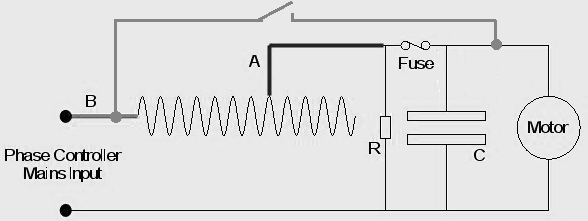
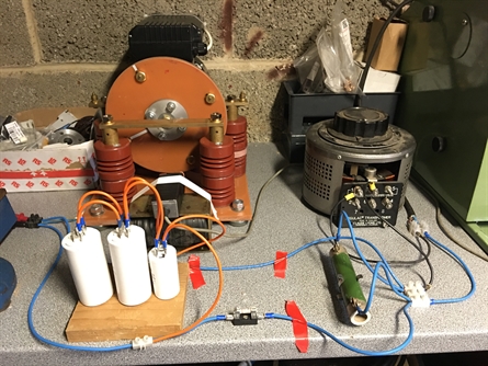
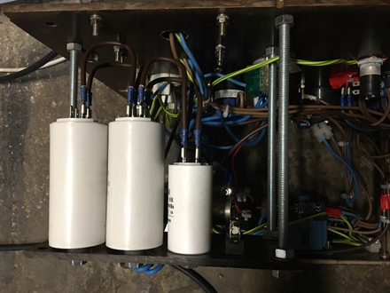
The switch in top of the diagram is only there so the motor can start with out any phase shift (less load on the motor), the resistor R is there to bleed down the capasitors when the system is powered down, the picture below left is the first "bench" test of the system, then the picture below right is the phase controller intergrated in to the control box.
The components used are as follows.
2 x 650V at 40uF caps
1 x 650V at 10uF cap
1 x 10k ohm resister
1 x 8A variac
2 x 650V at 40uF caps
1 x 650V at 10uF cap
1 x 10k ohm resister
1 x 8A variac
Copy right 2021